
Preconditions
-
SOTO is turned on and has an active wireless network connection
-
The environment has been mapped and modelled with driving routes and points-of-interests
-
Active SOTO receives VDA5050 orders from a warehouse management system through a master controller system
-
All errors have been acknowledged and the emergency stop button has been released
-
SOTO is in automatic mode
-
Robot is localized
Tour execution
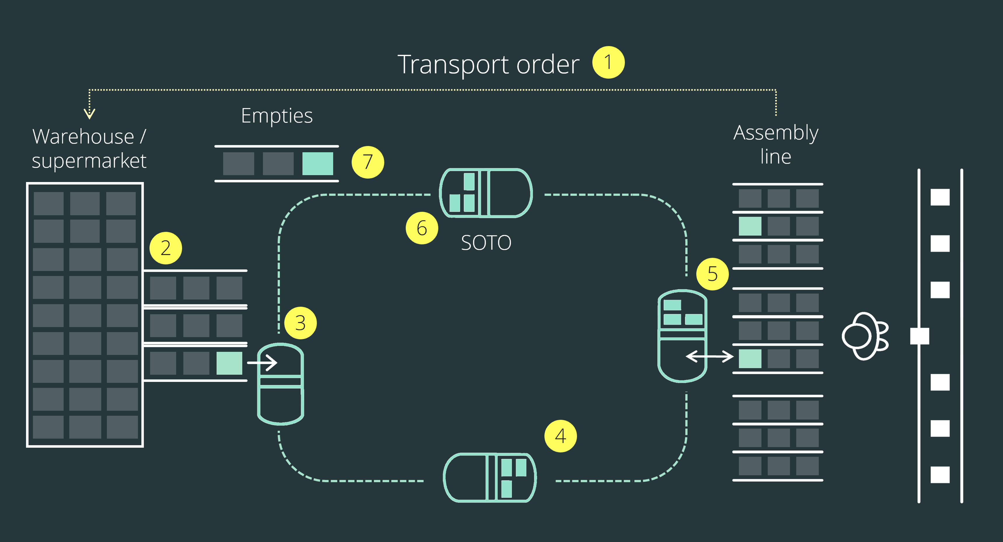
In general, a SOTO transport could look as follows:
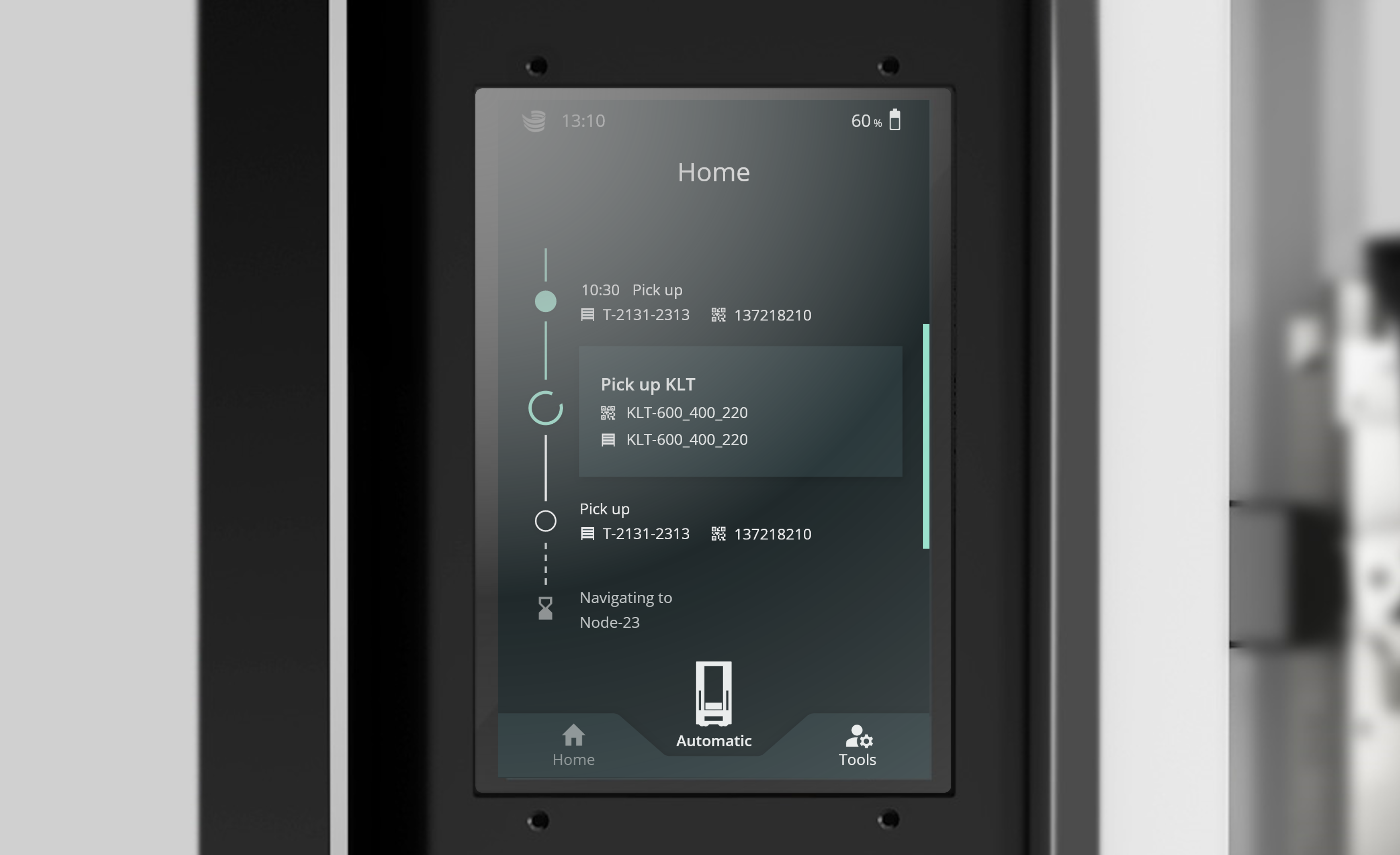
Status display
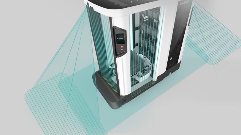
Environment perception
In order to understand the behaviour of SOTO better, it's important to understand how the robot perceives its surroundings.
Sensor setup - Top laser Scanner
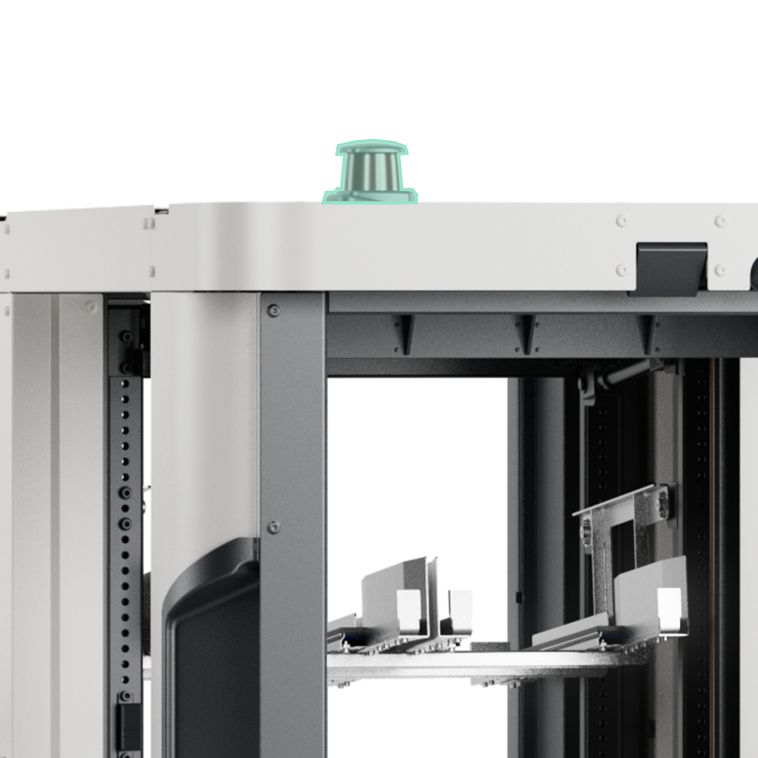
Top laser scanner
SOTO is fitted with a 360° laser scanner on top of the robot.
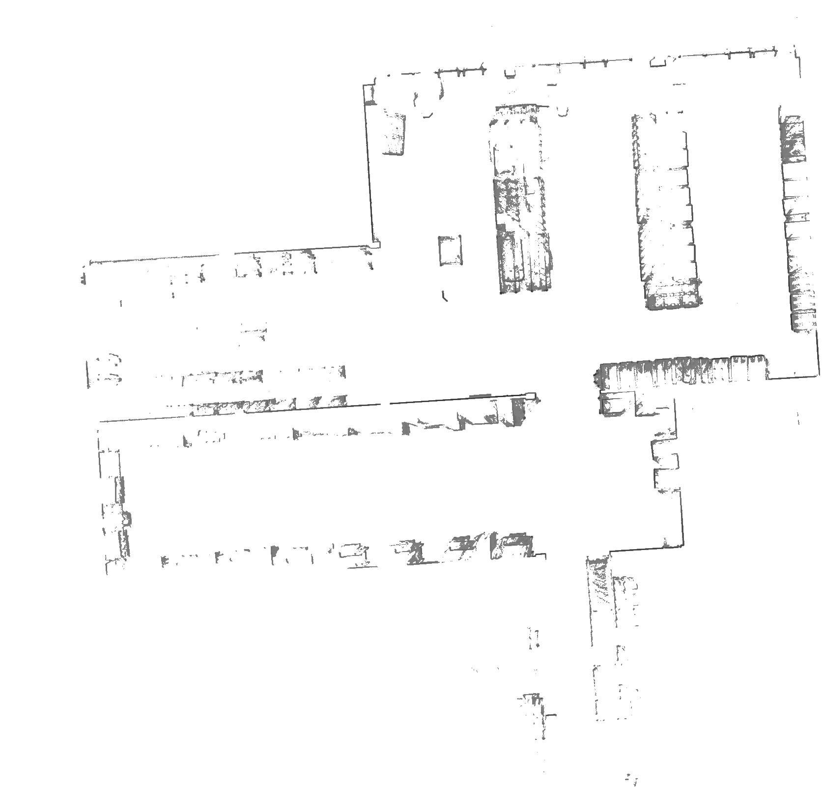
This laser scanner records the localization map at a height of 2.2 m. At this height, there are usually fewer obstructions and changes in the environment, which makes localization more stable.
The primary function of this laser scanner during live operation is localization.
The top laser scanner also has a safety field function that stops the robot when it gets too close to an obstacle.
Sensor setup - Bottom Laser Scanner
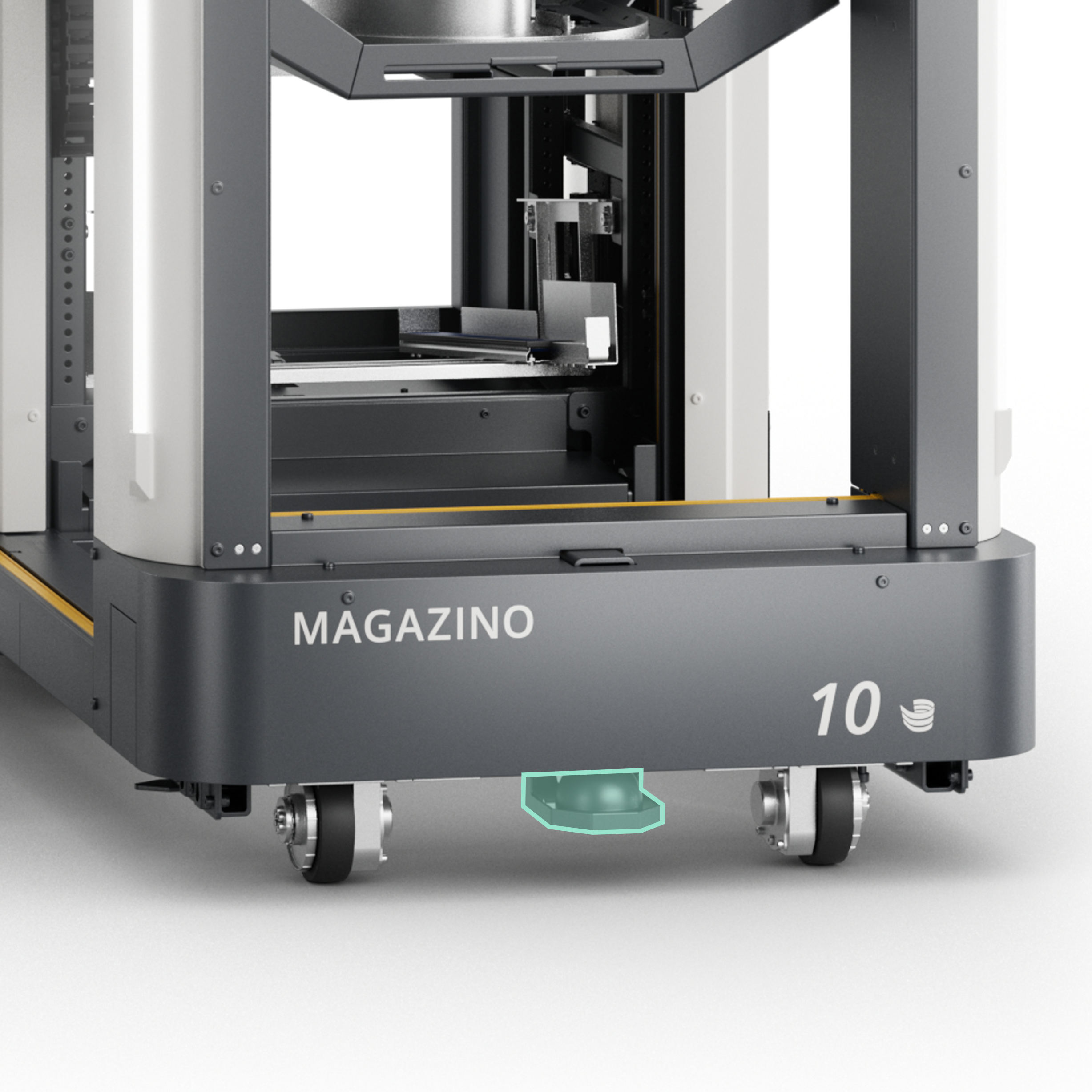
Bottom laser scanners
SOTO is equipped with three laser scanners on the bottom of the drivebase that span a 360° safety field. One laser scanner is mounted in the front and two in the back underneath the backpack.
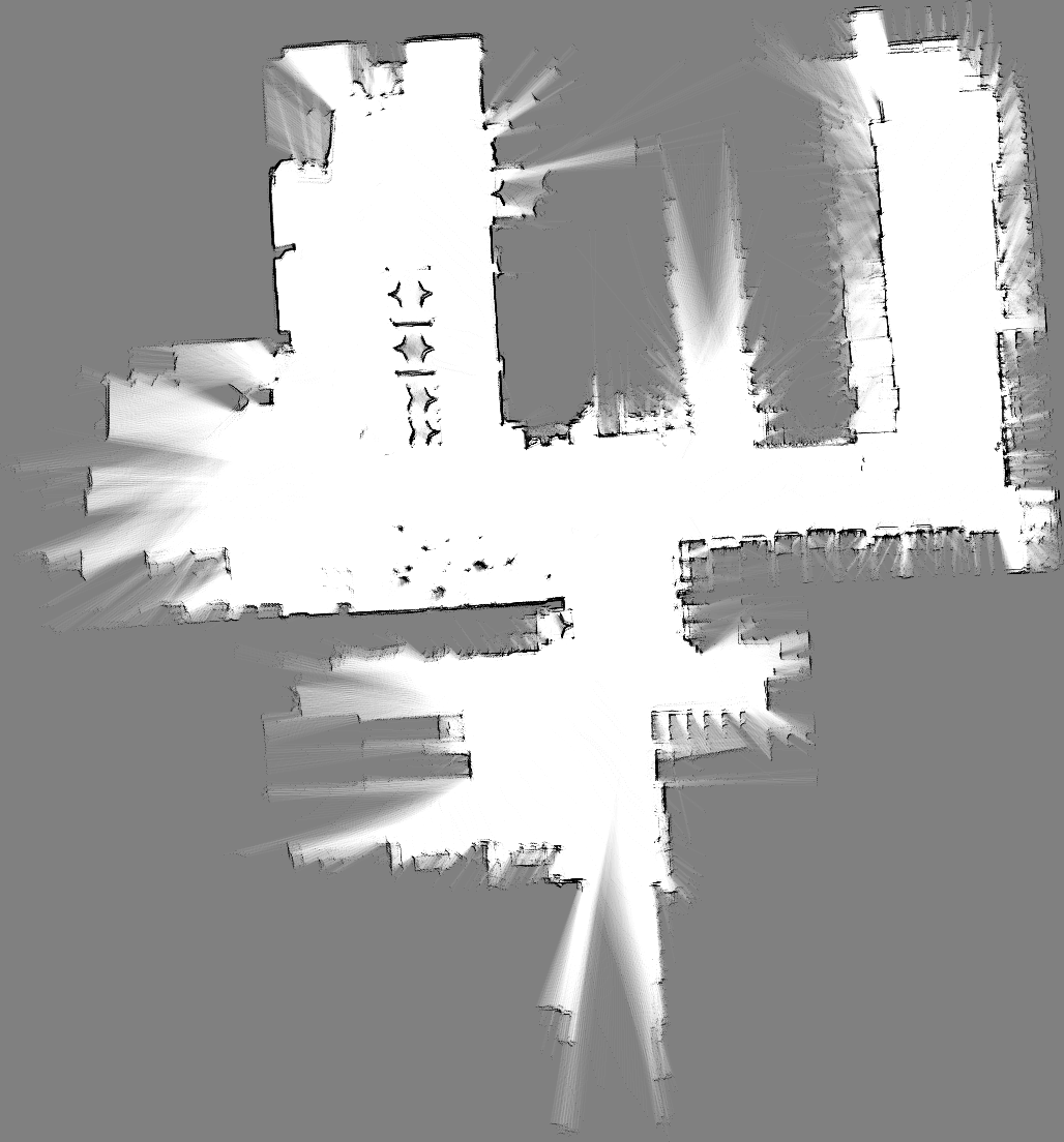
These laser scanners record and map the environment at a height of 0.12 m.
The main functions of these laser scanners during live operation are safety and navigation. If SOTO comes too close to an object or a person, the robot stops automatically.
Sensor setup - 3D camera
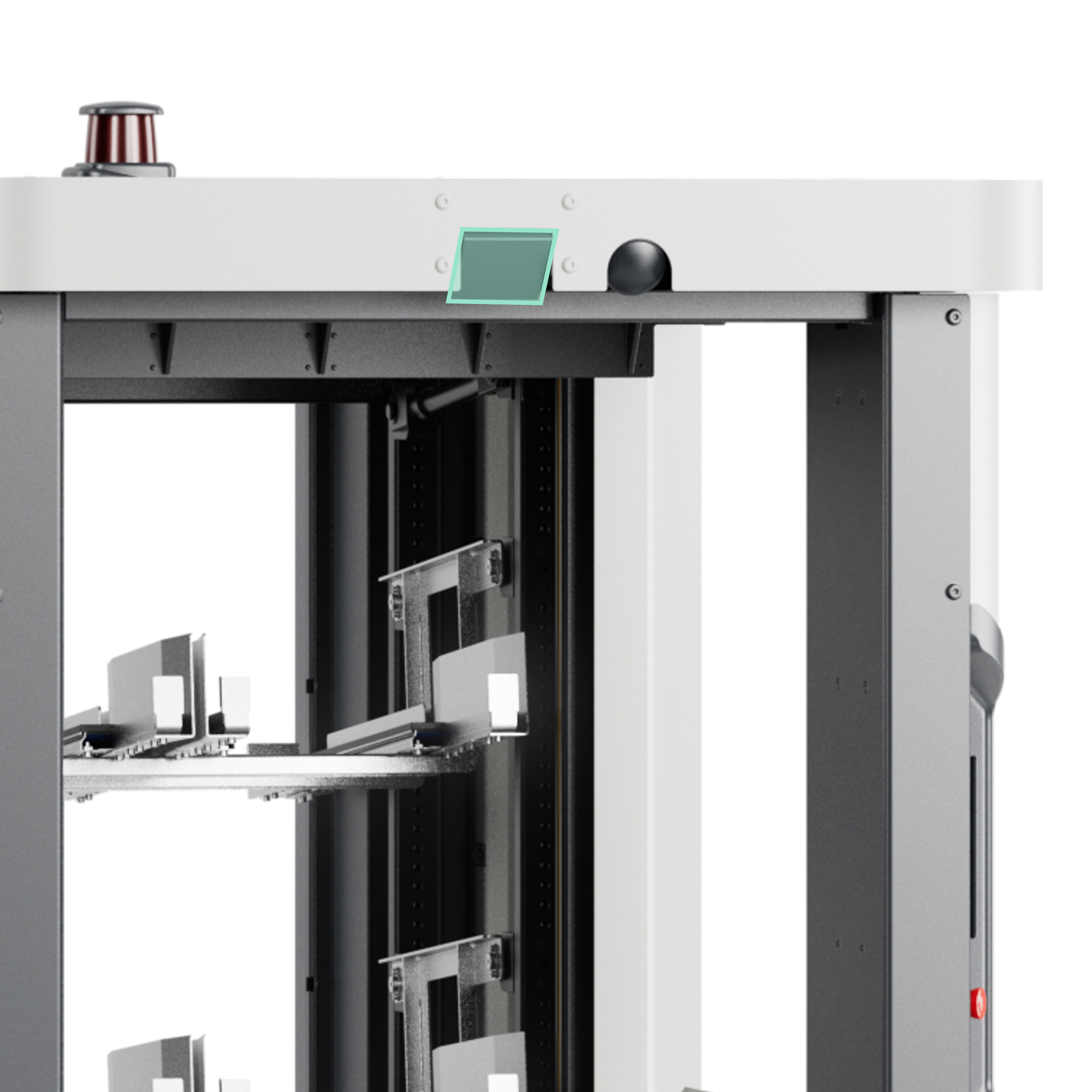
3D cameras
SOTO is equipped with two 3D cameras. One is positioned at the top of the robot frame in the front, and the other at the opposite side in the rear.
During live operation, these cameras create a point cloud of the surroundings in the direction of travel, which can be used for navigation and obstacle avoidance.
Localization map
|
Localization map The localization map is recorded by the top laser scanner and depicts a 2D cross-section of the area at a height of 2.2m. The top laser scanner is used as it has a longer range and the ability to detect fixed structures. During live operation, SOTO compares this map with the sensor readings of the robot to correctly position itself in the physical environment. |
Environment map
|
Environment map The environment map is recorded by the bottom laser scanners and depicts a 2D cross-section of the area at a height of 0.12m. This map shows the positions of shelves and obstacles at ground floor level (notice the star docking shapes). The map is used to create a virtual model of the environment, which users can edit by adding handover stations, shelves and a navigation graph in the Environment Editor. |
Modeling
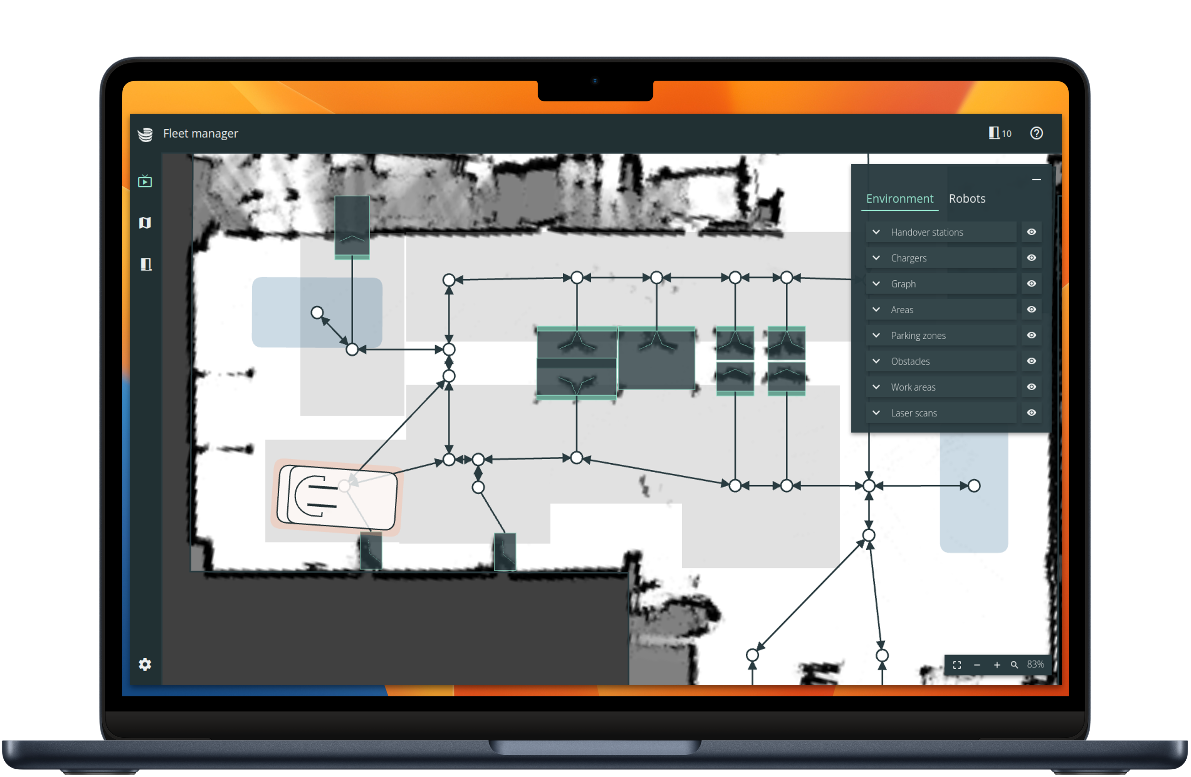
Modeling elements

|
Working area Permitted area that SOTO operates in and is not allowed to leave. |

|
Shelves Shelves with compartment configuration and identifiers. |

|
Zones Reduced speed zones. |

|
Obstacles Obstacles within the working area. |

|
Driving graph Graph which SOTO navigates along, with permitted driving directions, robot orientation and deviation tolerances. |

|
Chargers Location of SOTO charging stations. |

|
Parking spaces Location of SOTO parking spaces. |
Navigation
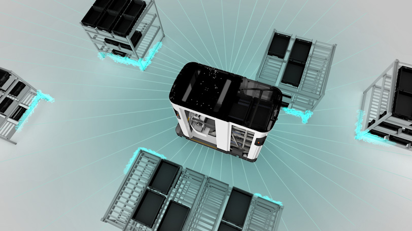
During live operation, SOTO moves through the working area autonomously. The robot localizes itself through the contour readings of the top laser scanner in the physical environment.
The robot drives to its target location within the permitted tolerances of the driving graph. The exact path taken by the robot and its speed are determined by the readings of the bottom laser scanners and 3D cameras.
Obstacle avoidance
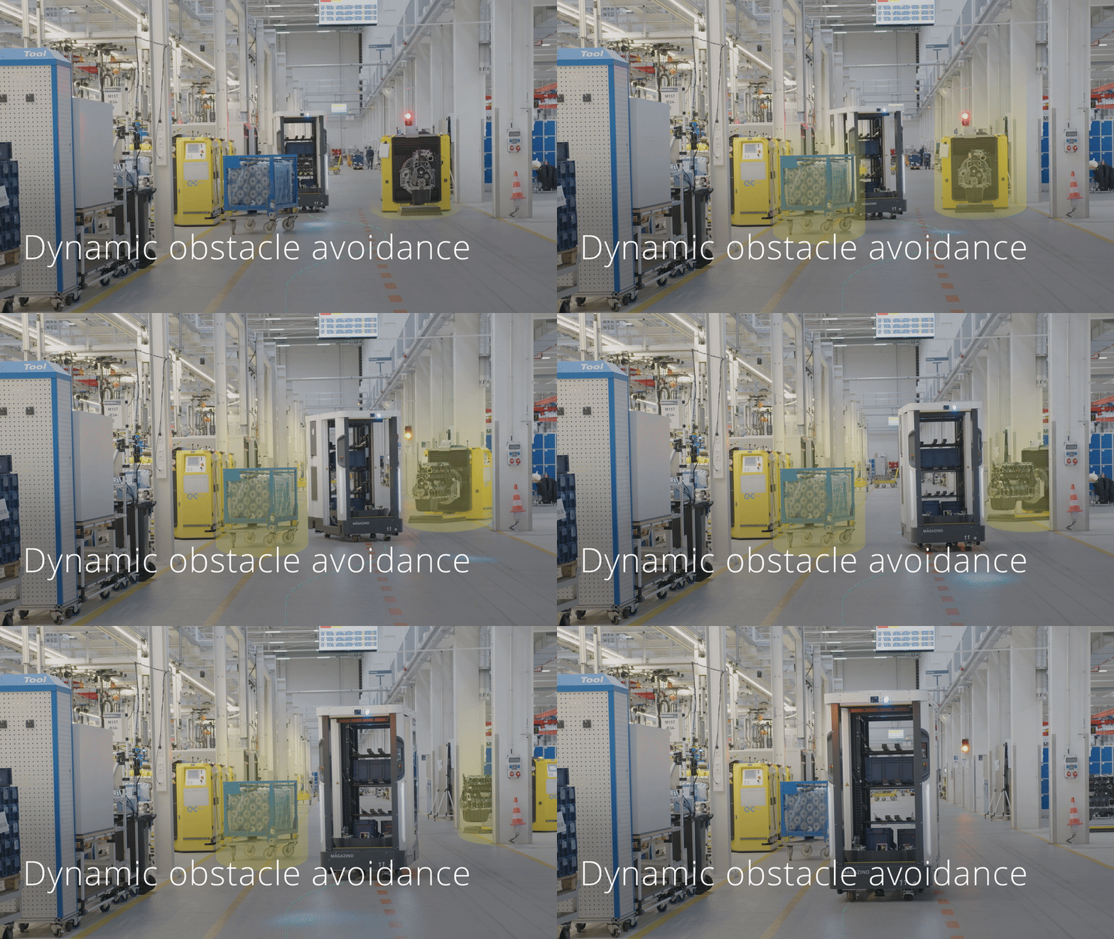
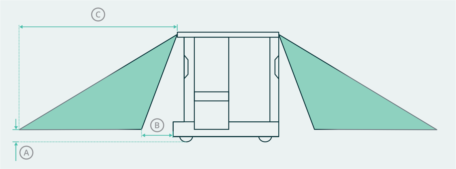
The navigation path is not static. If SOTO detects obstacles along its way with the 3D cameras, the navigation path is replanned so that obstacles can be avoided. The obstacles can only be avoided if the tolerances allow enough room for maneuvering off the driving graph.
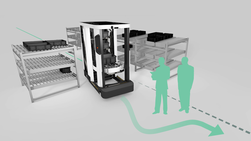
Obstacle detection is used to navigate around obstacles outside the field of view of the laser scanners. Obstacle detection is not part of the safety concept.
Video: Obstacle avoidance
Detection range
|
Obstacles |
|
|
|---|---|---|
|
Minimum detectable obstacle size (L × W × H) |
|
100 × 50 × 50 mm |
|
Minimum height above the ground |
A |
70 mm |
|
Effective range in the direction of travel |
B – C |
700 mm – 2700 mm |
|
Materials |
|
Metal (matt), plastic, paper, and cardboard |
Docking
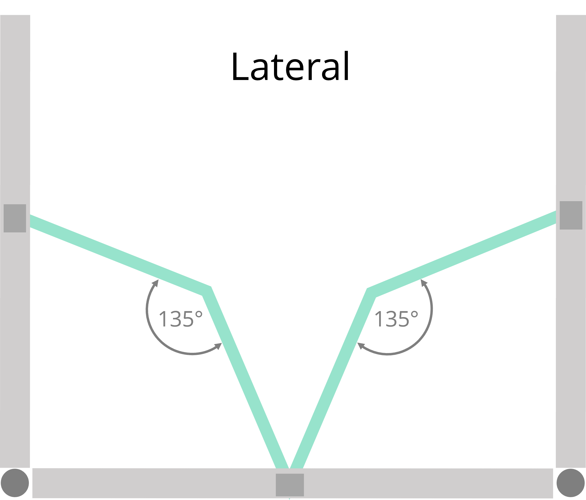
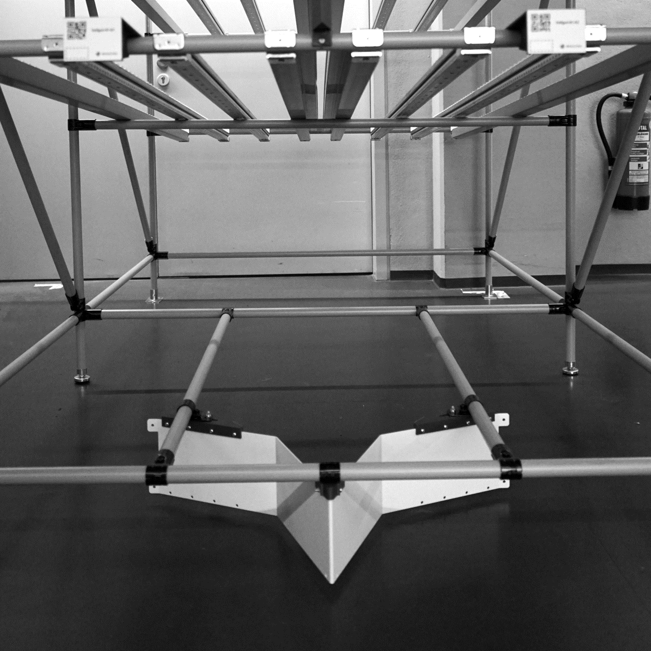
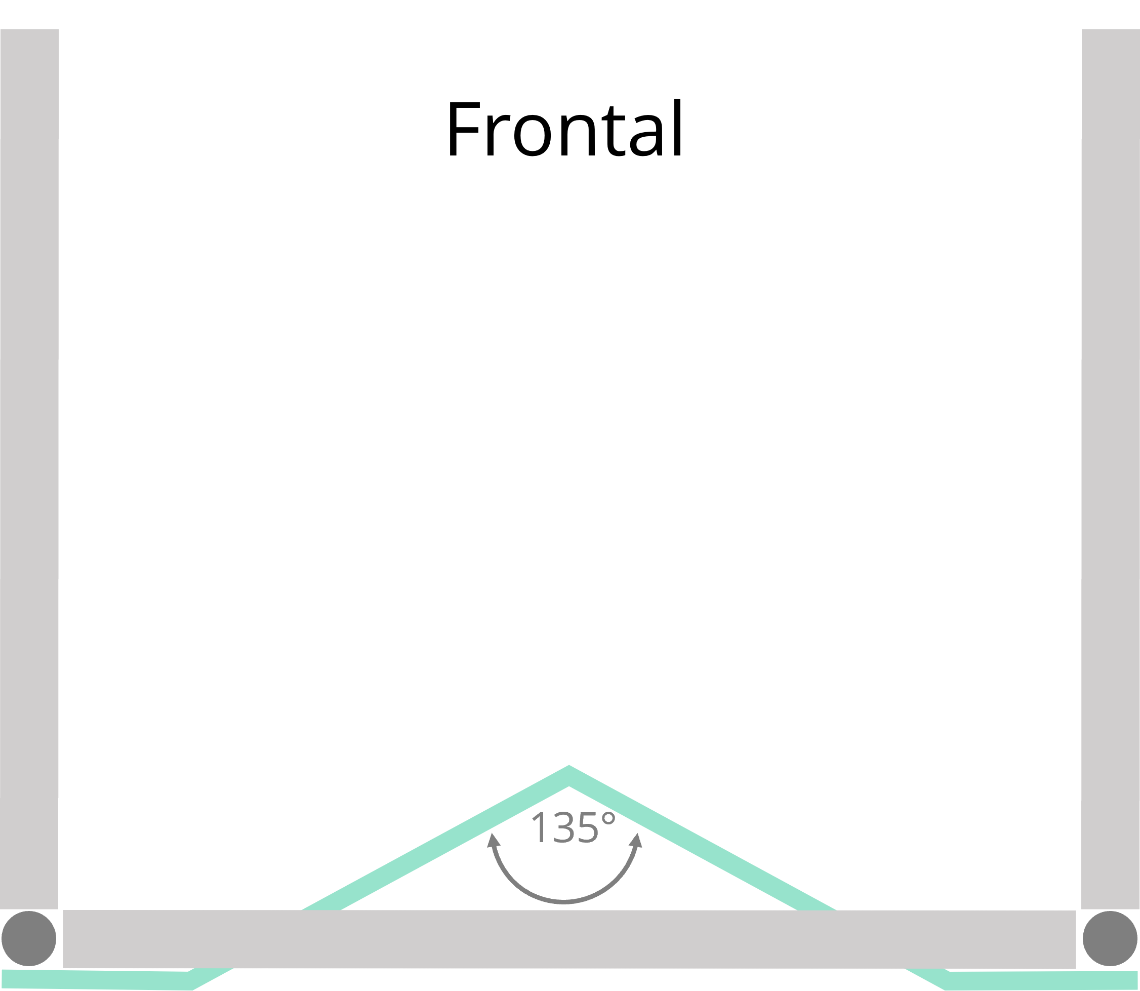
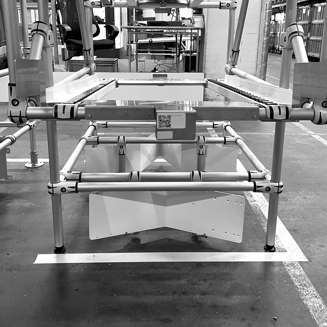
All shelves need to be equiped with one of three possible docking shapes:
Bottom docking shape
”Star-shape”
Bottom docking shape
”V-shape”
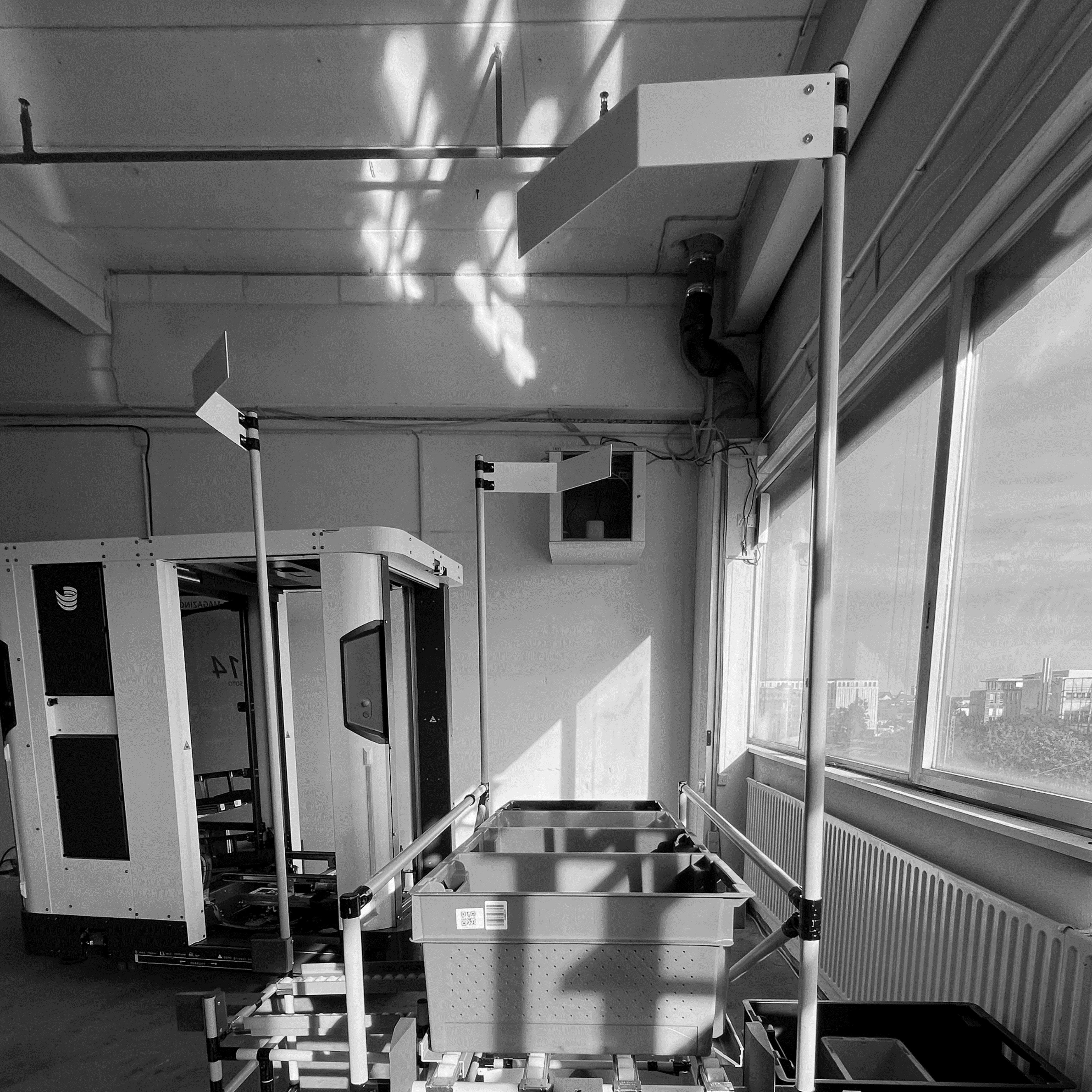
Top docking shape
”Flag”
Docking shape mounting options
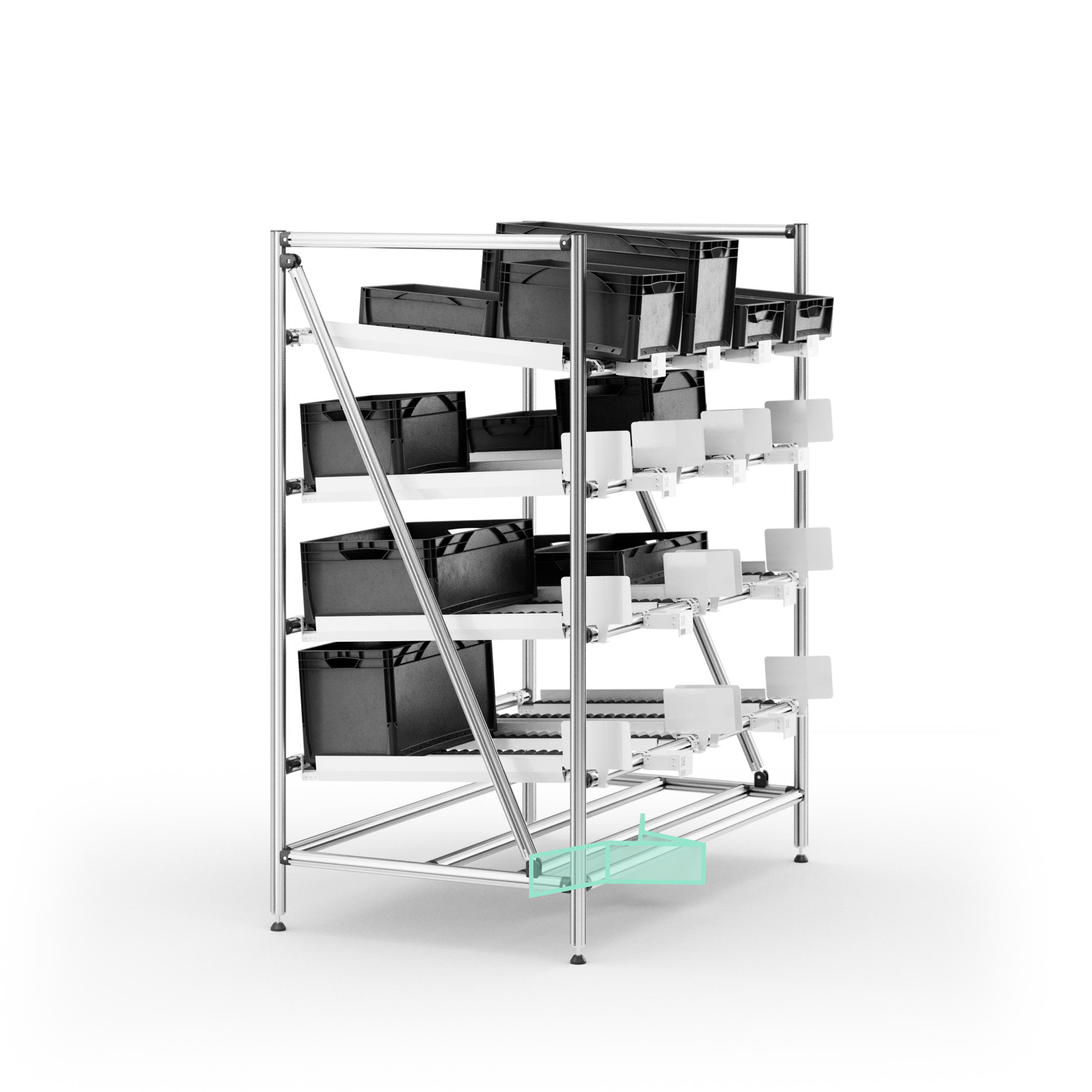
Mounting at bottom laser scanner level (0.12 m)
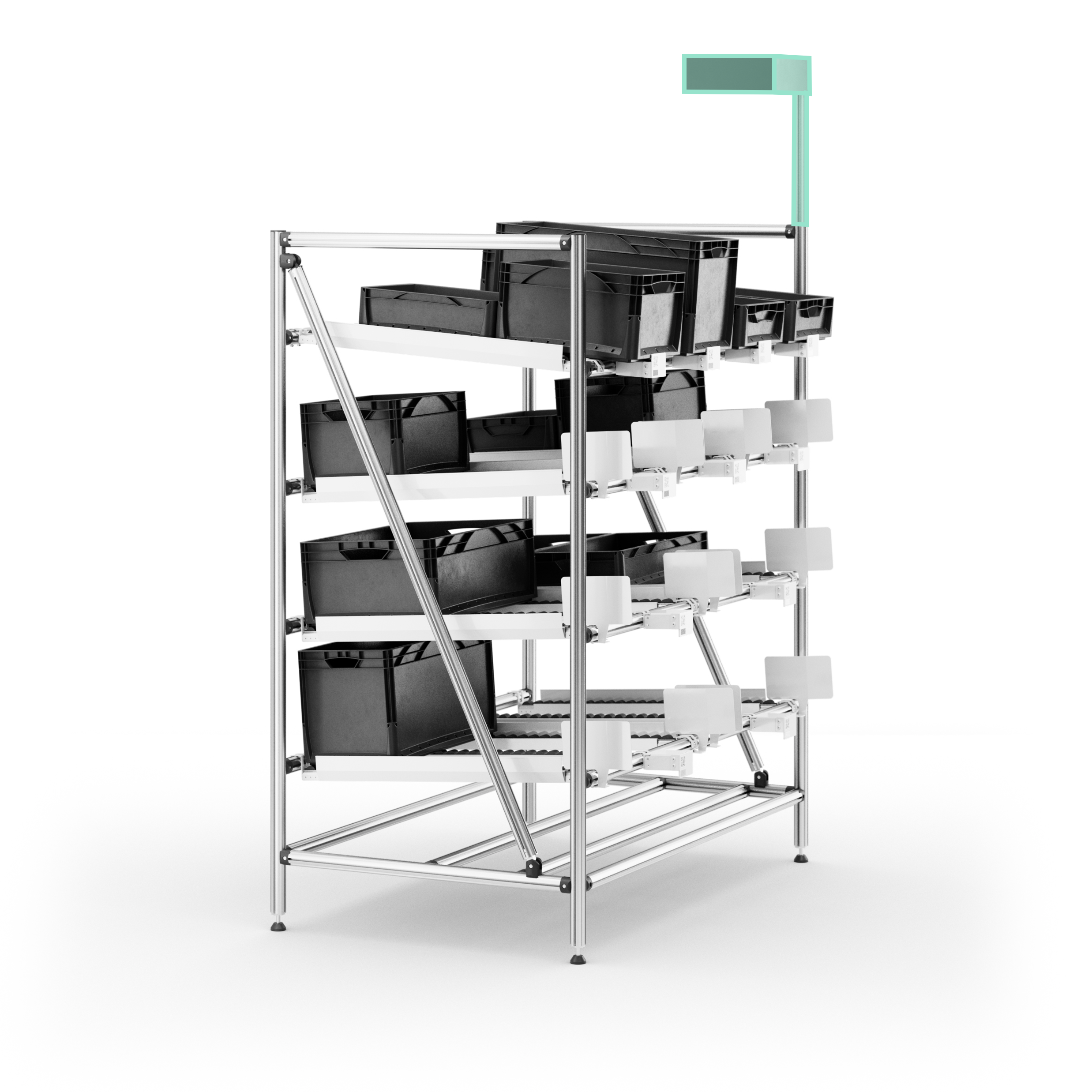
Mounting at top laser scanner level (2.20 m)
Shelf positioning tolerance
Once SOTO detects the docking shape it positions itself precisely in front of the shelf. The robot compensates for any positioning offsets the shelf may have from the modelled environment.
SOTO is capable of adjusting for deviations of the shelf from its original position, as detailed below:
|
Maximum lateral offset between real and modeled position of the handover station |
+/- 200 mm |
|
Maximum angular offset between real and modeled position of the handover station |
+/- 5° |
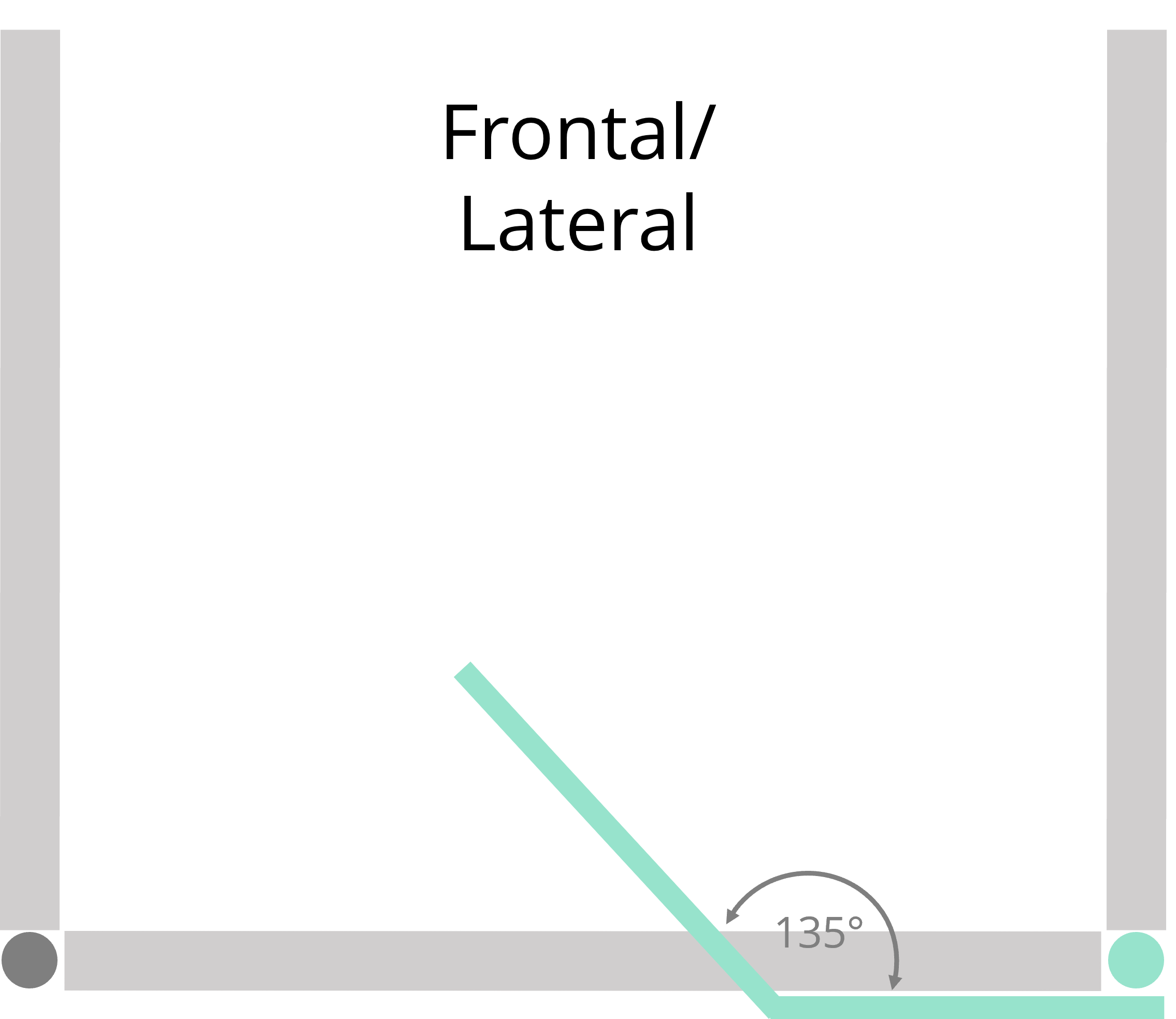
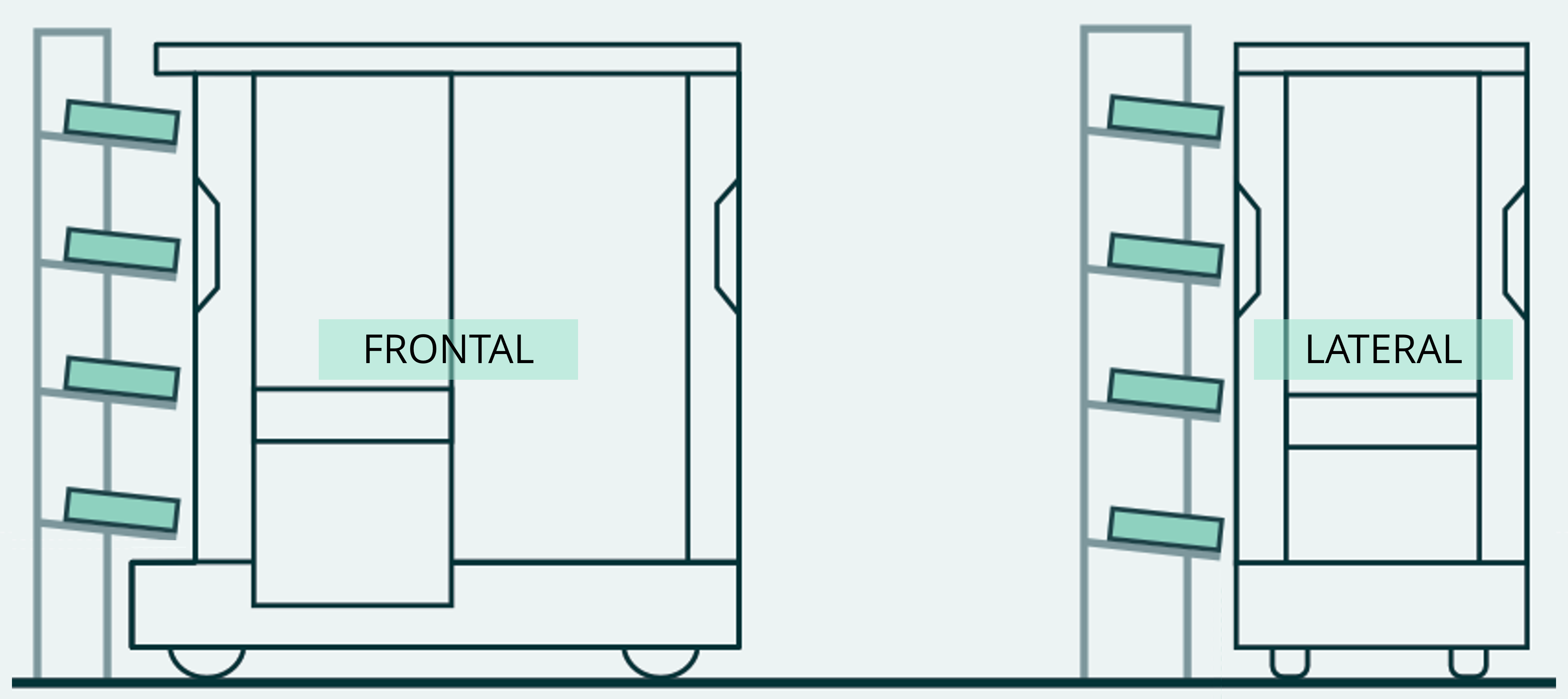
Docking orientations
SOTO can perform a frontal or lateral docking maneuvre, depending on the type of docking shape used and the settings made during installation.
Compartments
SOTO uses the optical sensors on the gripper to detect the compartment and load carrier.
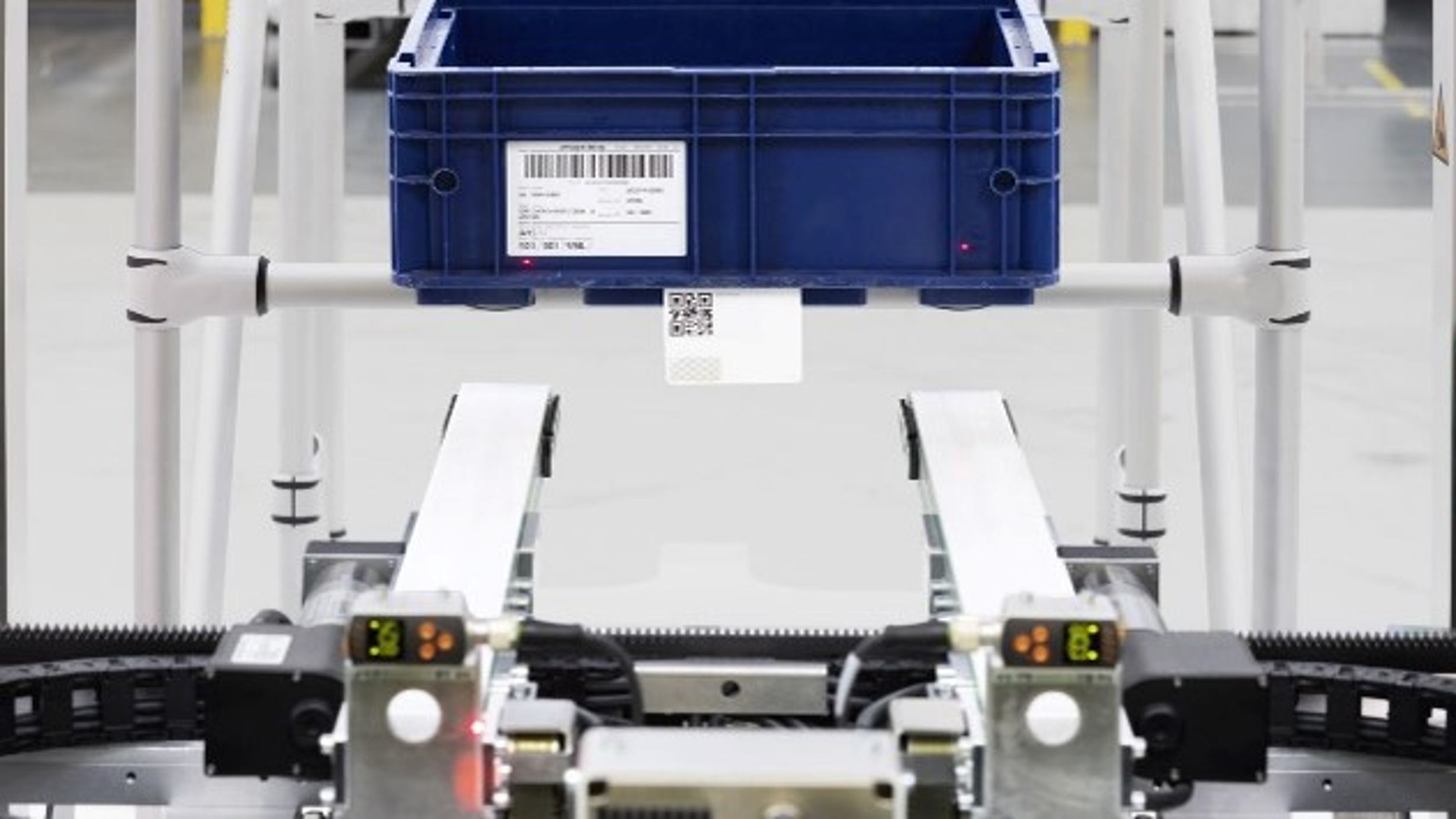
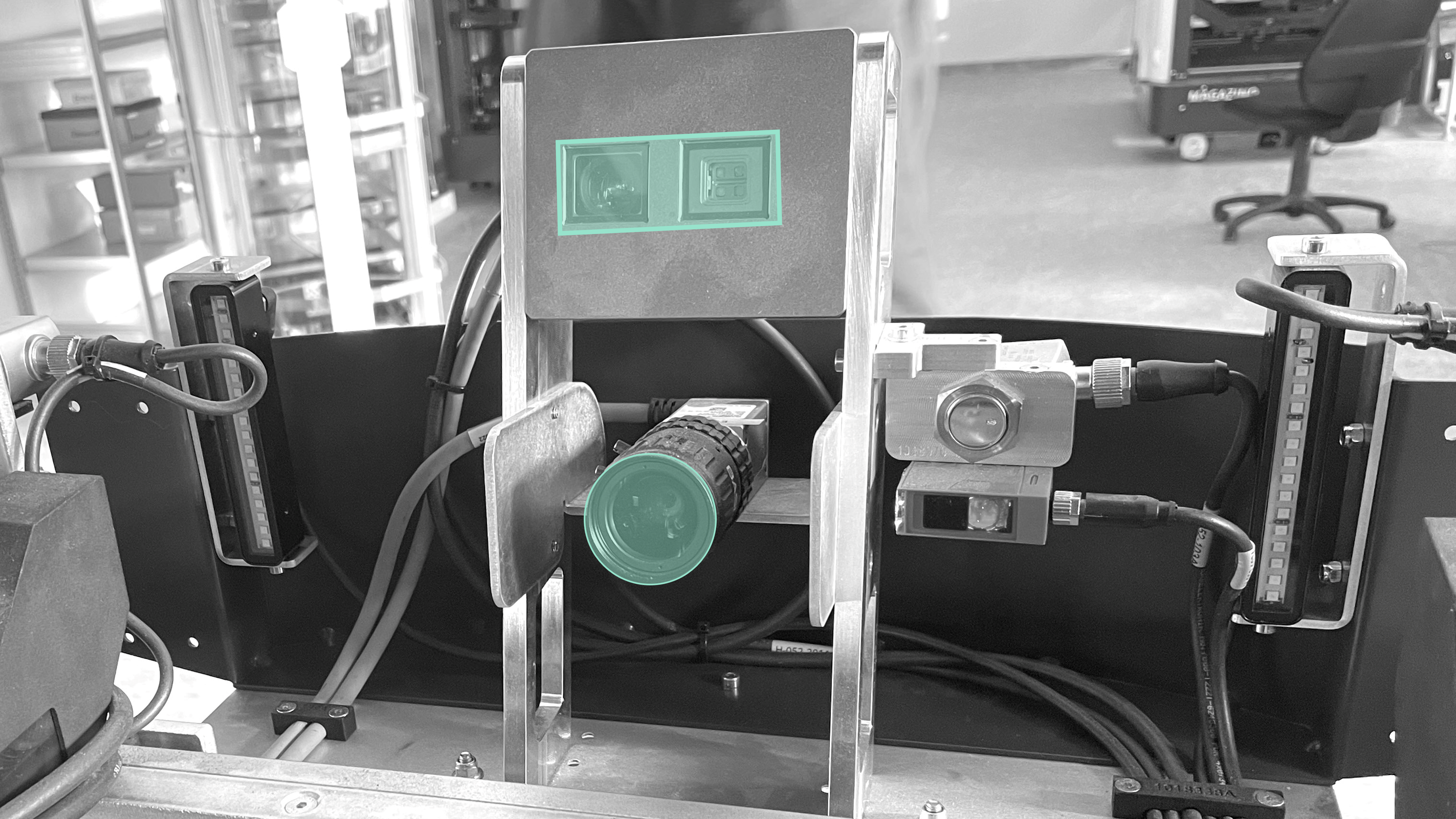
Gripper cameras
There are two cameras in the gripper for this purpose:
-
High-resolution 2D camera for detecting barcodes
-
3D camera for measuring distances towards KLTs
Compartment adapters
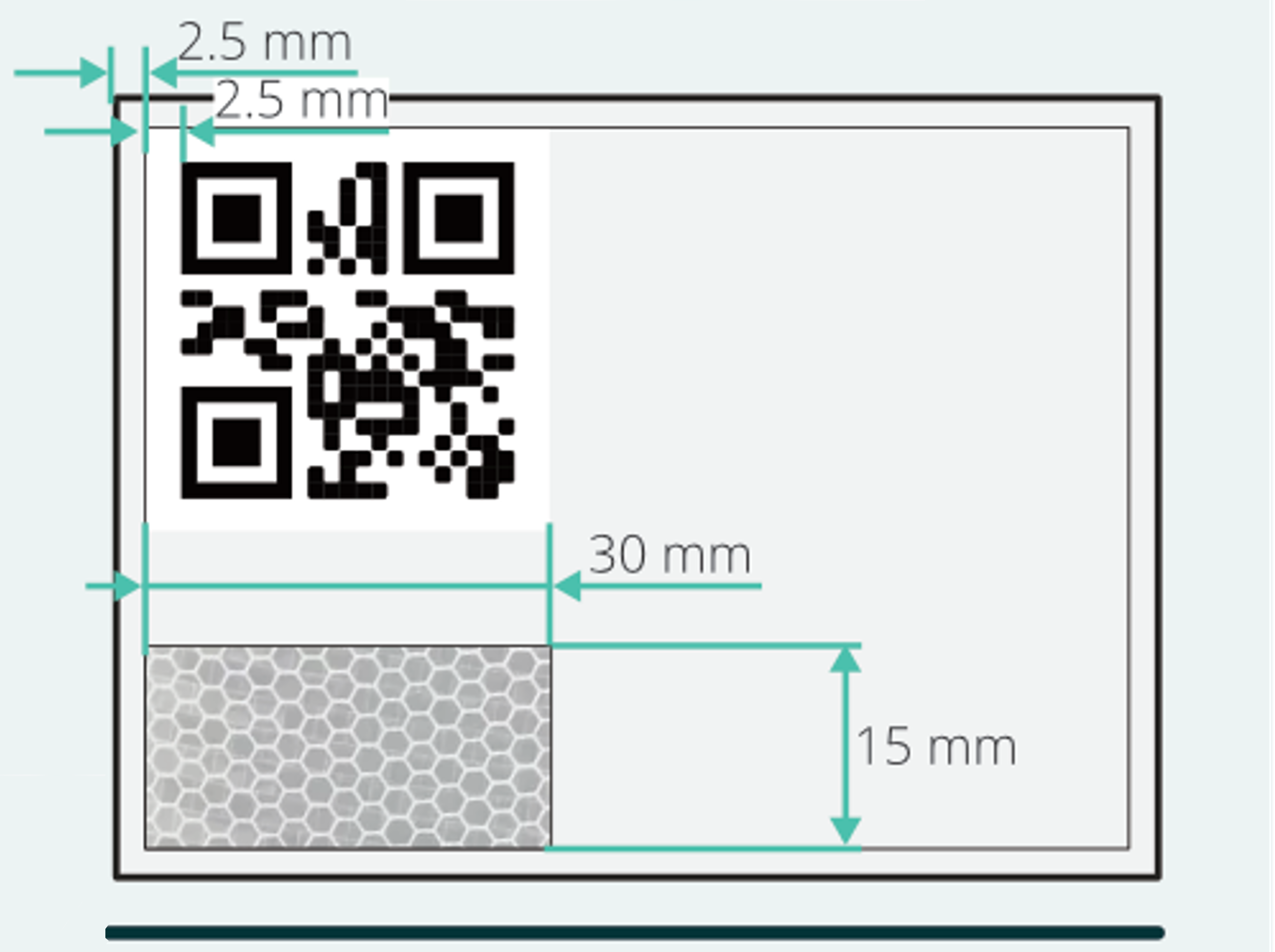
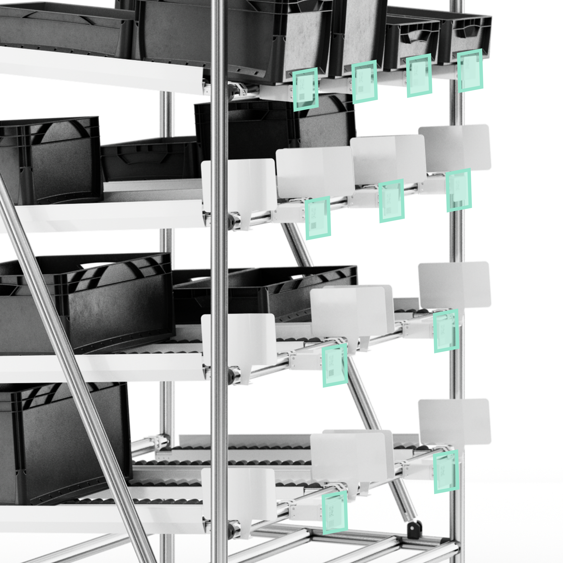
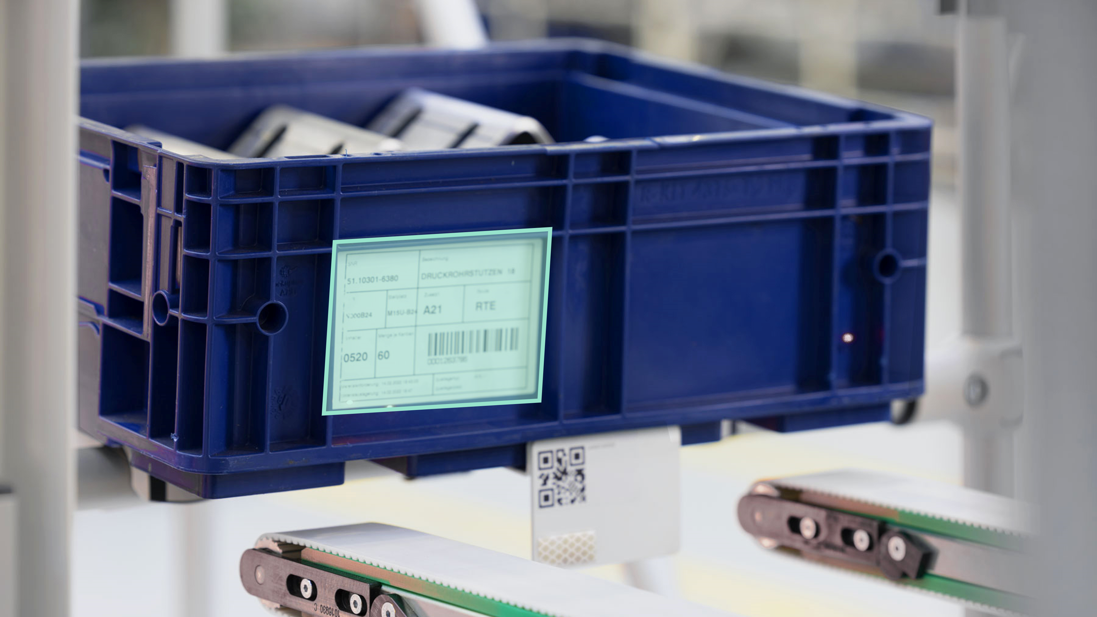
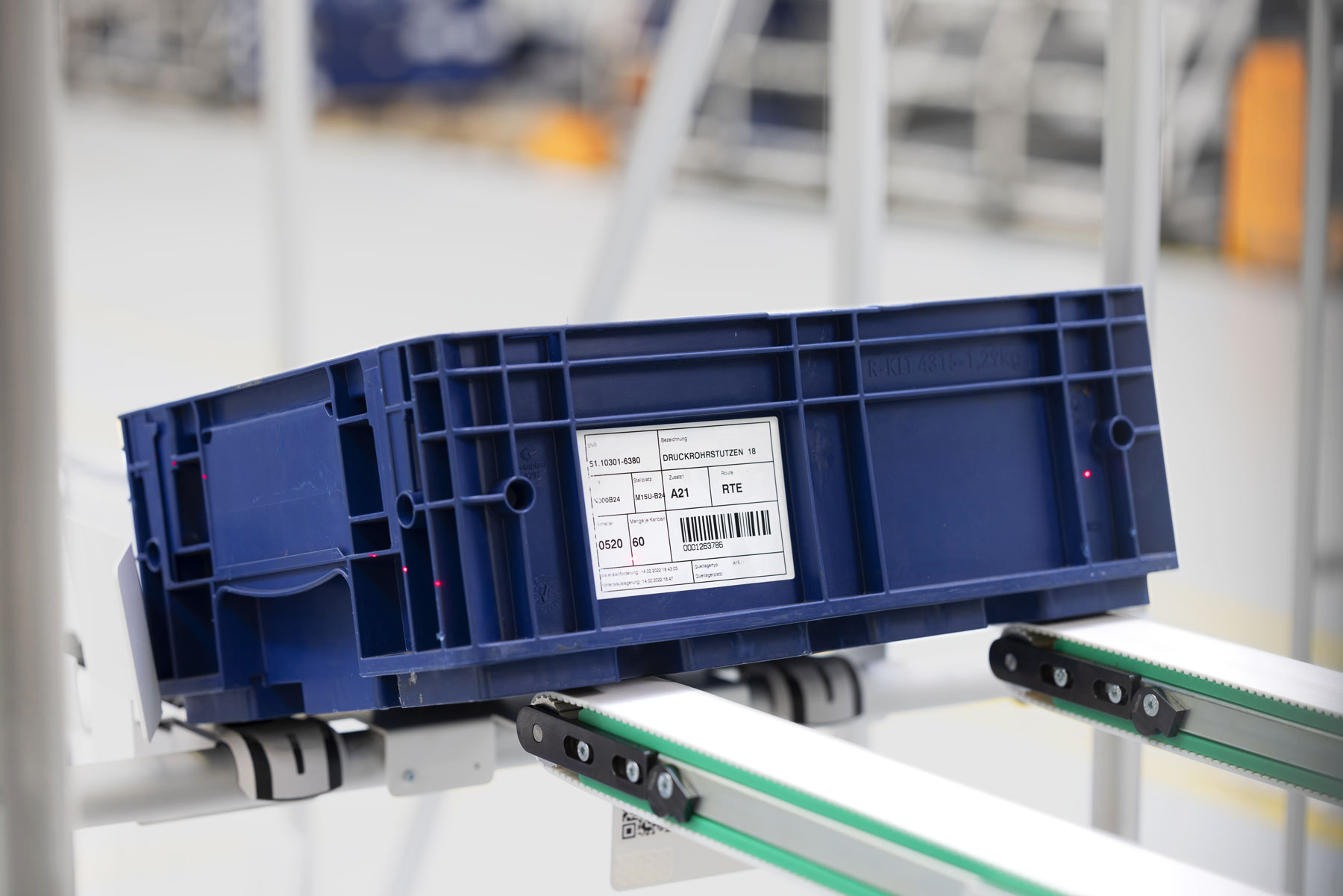
Each shelf compartment needs to be fitted with a pick-up or put-down adapter, depending on whether the compartment functions as a source or sink for load carriers. The adapters are made up of two main components: positioning funnels that guide the robot's actions, and a compartment identification panel. This panel includes a QR code, the compartment's name and a reflective tape strip.
The compartment identification panel must strictly adhere to the specified dimensions as follows:
Load carrier identifier
|
Types of identification codes on objects |
QR, DataMatrix, and Code128 |
|
Minimum line width of 1D barcodes |
0.33 mm |
|
Minimum module width of 2D barcodes |
0.33 × 0.33 mm |
|
Label surface condition |
non-reflective |
Pick-Up & Put-Down
Pick-up
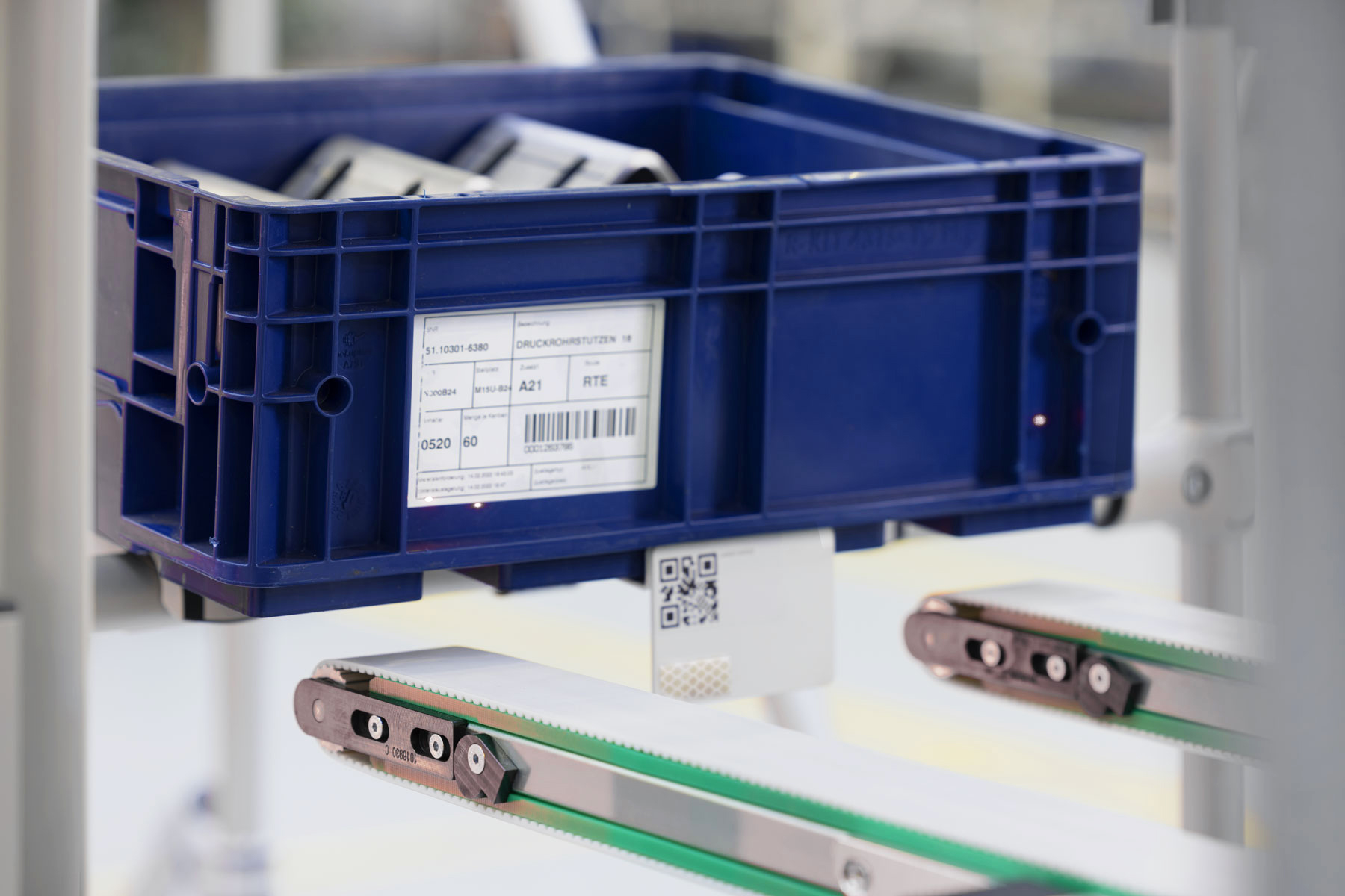
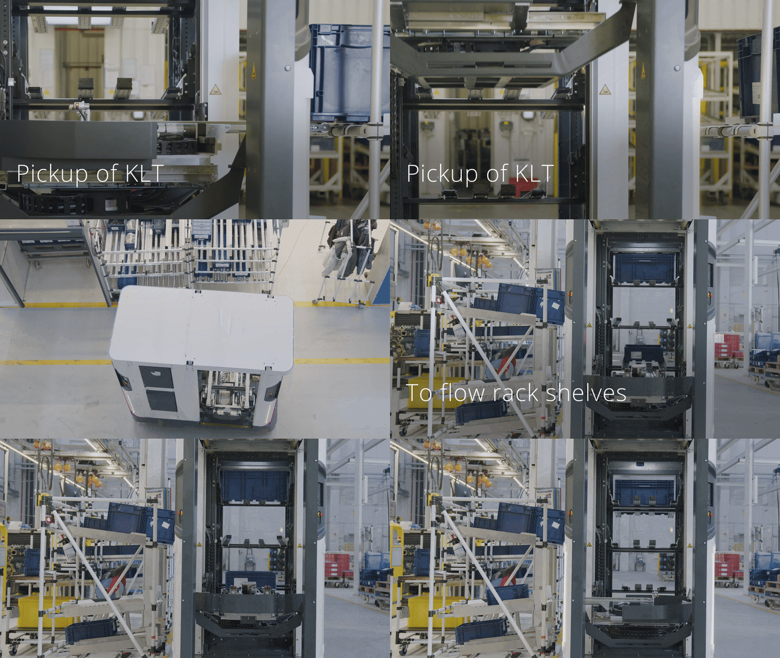
Once SOTO has detected the correct compartment and load carrier, it gently lifts the load carrier with the gripper and then retracts it with the conveyor belts of the gripper.
Put-down
When placing a load carrier into a compartment, SOTO inserts it into the positioning funnel using the conveyor belts of the gripper and lets it slide into the compartment.
SOTO ensures that the compartment is empty before putting down a load carrier.
Video: Pick-Up & Put-Down
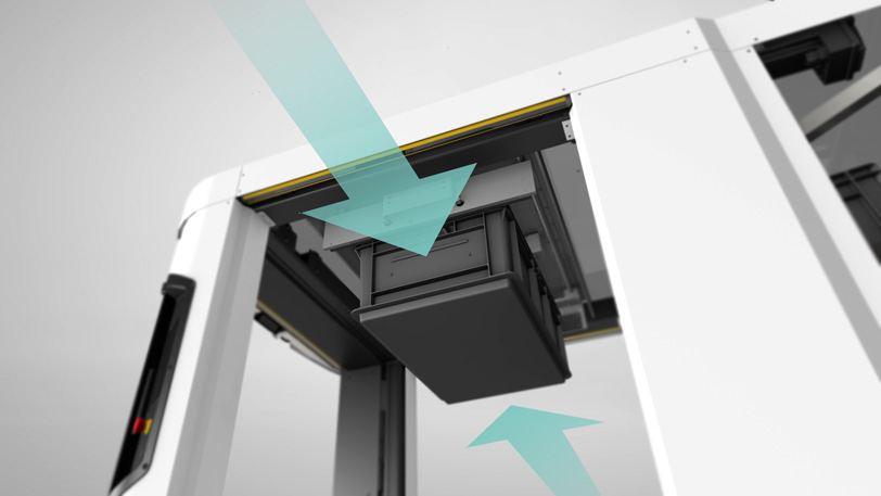
Load carrier rotation
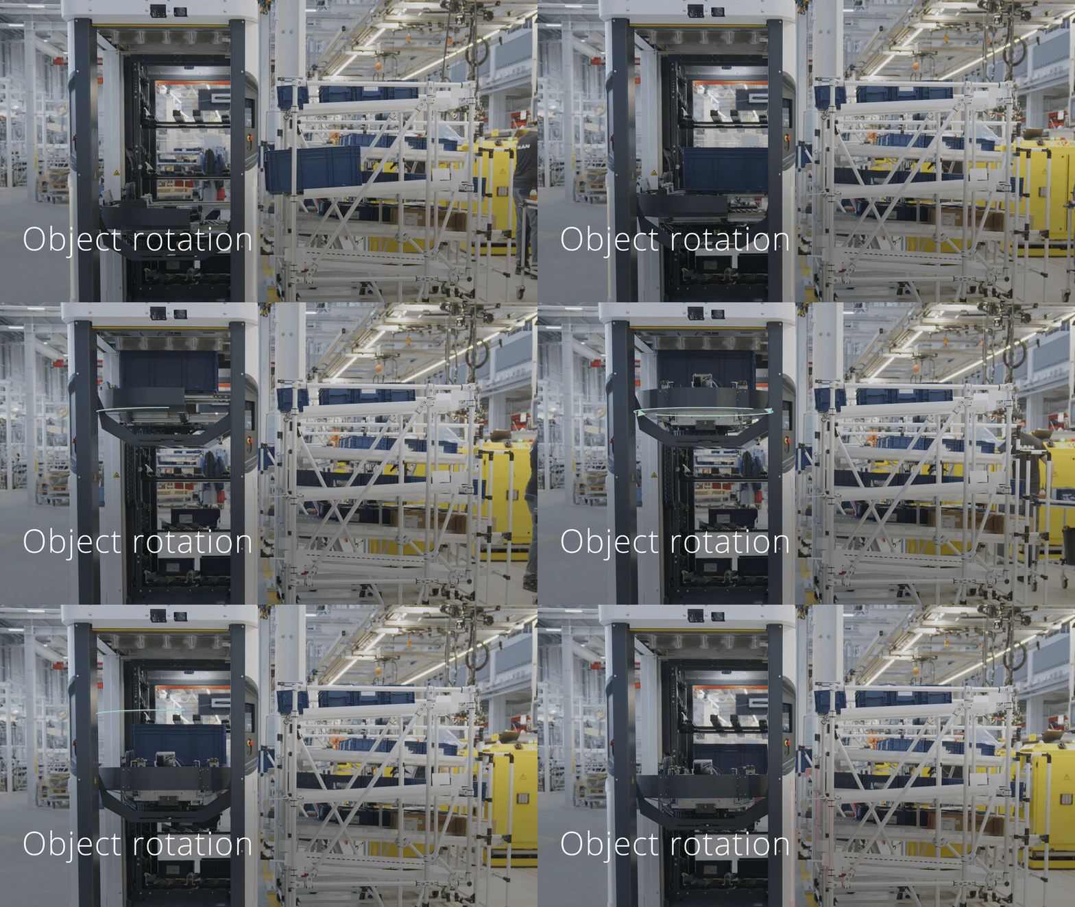
If the orientation of the load carrier does not match the backpack or shelf compartment, SOTO will rotate the load carrier by 90°. This is achieved by the clamping unit in the ceiling above the gripper.
As soon as the load carrier sits on the gripper, it is lifted to the ceiling and firmly clamped. The gripper then rotates 90° underneath the load carrier. The load carrier is then released onto the gripper with an alignment that matches the backpack or shelf.
Video: Load carrier rotation
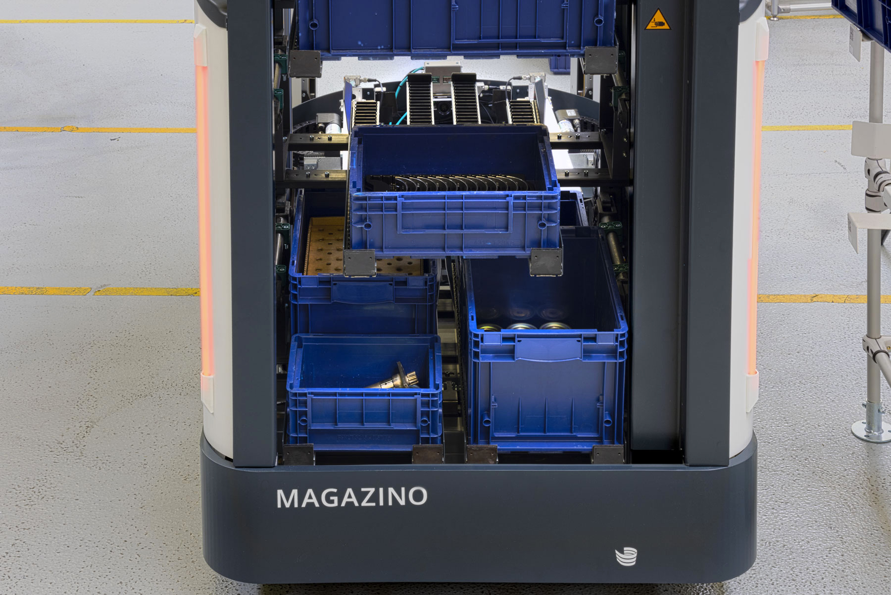
Backpack
Error recovery
If an error occurs, SOTO uses its light indicators to notify nearby staff. To assist in resolving the issue, SOTO presents an error report and a recovery tutorial on its display.
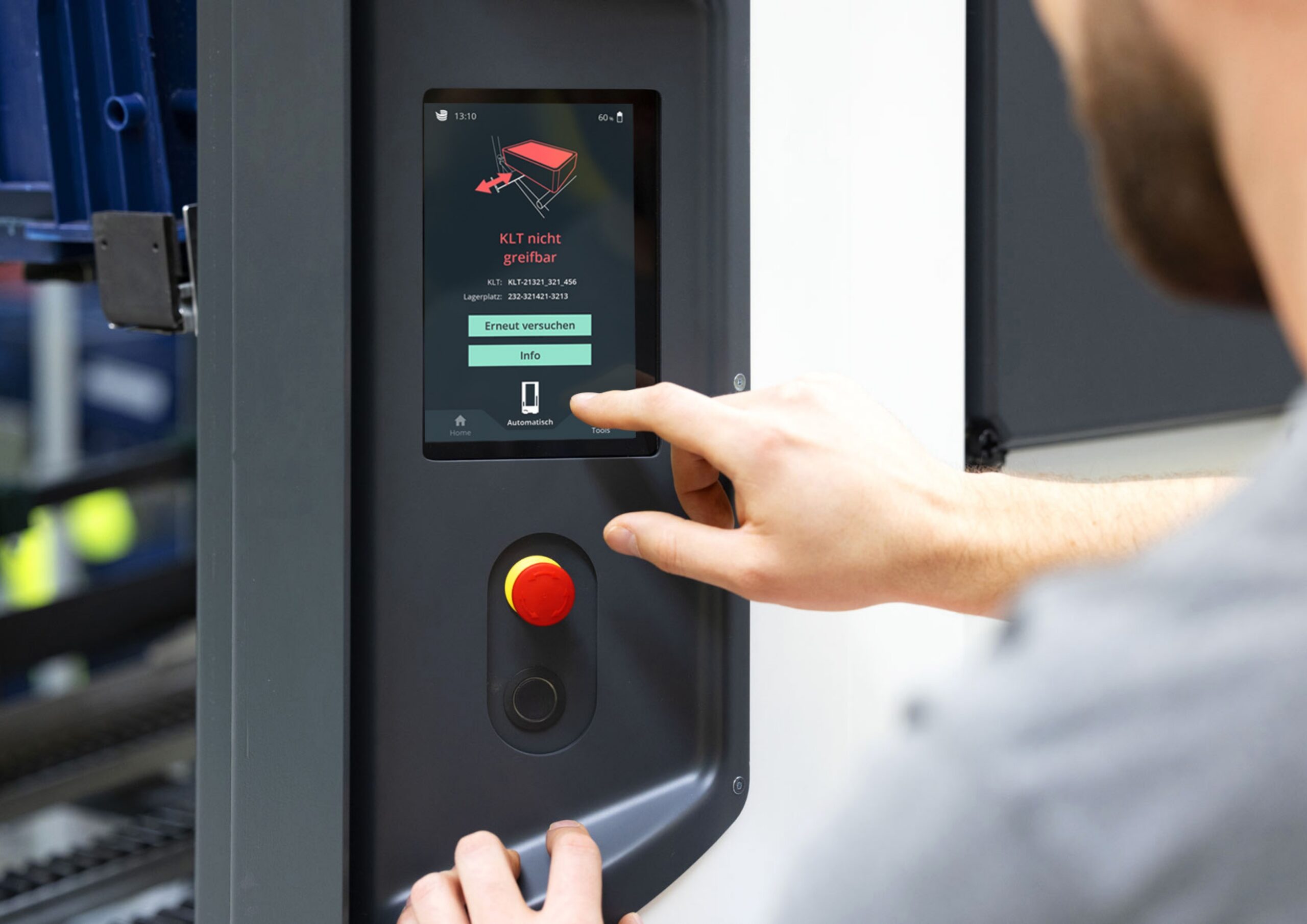
Staff can rectify the problem by acknowledging the error and selecting a recovery option displayed on the screen.
Charging
As soon as the battery drops below a certain level, the robot automatically navigates to a charger. The charger is inductive and works without physical contact. While charging, SOTO will not accept incoming transport orders.
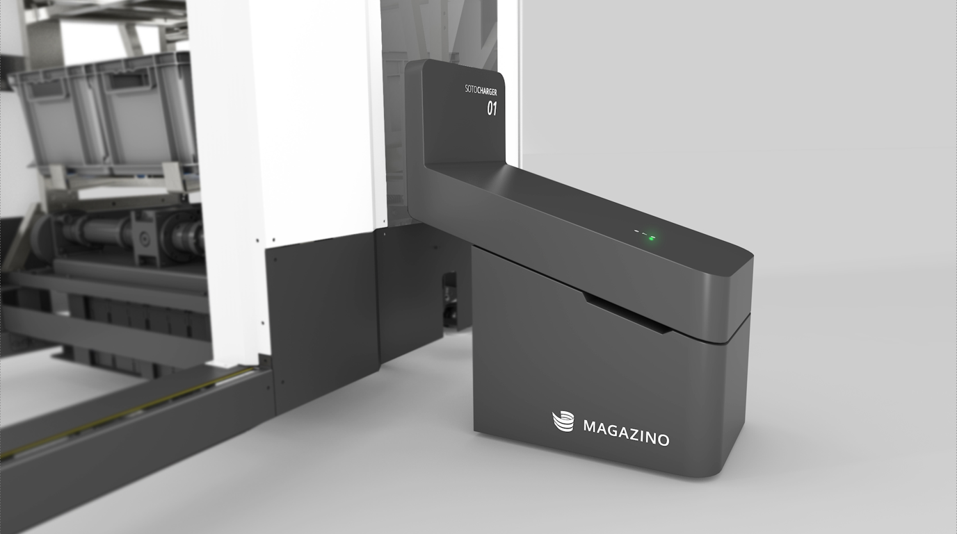
Once the battery has been charged up again SOTO is ready for new transport orders.